Analog Filters - Basics, First Order, Ideal Filters, RC Low Pass, Phasor Diagram, Bode Plot
Video Not Working? Fix It Now
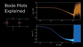
In this tutorial we focus on the very basics of passive analog filters. The most simple analog filter, a passive low pass filter, is described by the means of an RC circuit. In order to understand all it's implications, a simple capacitor, as well as some important descriptions of its behavior, like the bode plot and the phasor diagram, are elucidated.
Tutor: Michael Fuchs
Chapters:
0:00 Intro
1:12 Ideal Filters
3:15 The RC Low Pass Filter
7:16 Behavior of a Capacitor
10:04 The Phasor Diagram
12:45 The Bode Plot
16:27 Conclusion
Additional Links:
- How capacitors work:
https://www.youtube.com/watch?v=otQGdPLyF3w
https://www.build-electronic-circuits.com/how-does-a-capacitor-work/
- Free filter design tool:
https://rf-tools.com/lc-filter/
- Institute of Electronics / TU Graz: https://ife.tugraz.at https://www.tugraz.at
- Like us on Facebook: https://www.facebook.com/ife.tugraz.at
Production: TU Graz – Educational Technology
imoox
tugraz
technical
technology
university
graz
ife
electronical
basics
training
introduction
measure
measurements
basic electronics
tutorial
passive filters
crossover network
low pass filter
high pass filter
filtering
filtering 101
passive filter
bode plot
filter impedance
admittance
filter design
first order filter
1st order filter
phasor diagram
Comment